5.7.11

Seagate Dockstar - Accessible serial and JTAG port

Even though usually the Dockstar is accessible via ssh or web interface with OpenWRT, sometimes the onboard pin header comes handy either for using the serial console or for resurrecting a bricked device with JTAG. Therefore it is useful to have the pin header accessible even when the casing is closed. This is not an easy task to make in a nice way due to the clean and elegant look of the device. Previously this has been done by others with connecting only the serial port pins above one USB port, but I managed with all of the 10 pins as shown below. Be sure to have some 2 row 2.0 mm pitch receptors and headers before beginning this hack!
Also note that the warranty for the device will be void after such modification, therefore only do it if you 100% sure what you are doing!

First, I soldered a 10-wire ribbon cable between a 2x5 and a 2x7 receptor (both 2 mm pitch). The latter is important to be 2x7, as it will hold itself mechanically with the first and last unoccupied row (see picture on the right). The wire should not be longer than 8 cm, and should be connected in 90 degree to the 2x5 receptor. The point is that by connecting all the corresponding pins, all pins will be accessible from outside with the same wiring scheme as on the onboard header! It is also a good idea to have pin#1 marked with some paint (I used silver marker here).

As there are some openings on the upper casing, one of them has to be made a little bit bigger, so that the connector will fit in. In my opinion, these holes are merely for design and are not necessary for proper ventilation. Therefore it is appropriate to have them used for our purposes, as this will make virtually no damage on the elegant look of the device. 


First the upper casing has to be removed, as shown in my earlier post. Then the metal shielding has to be cut and removed to some extent as shown in the photo on the left. As it is apparent, I chose the side with the reset button, where there is enough space for an additional connector. The unnecessary plastic can easily be removed with a small rasp. First, remove the plastic between the two ventilation holes. Then an additional 3 mm has to be removed from the top as well in order to have the connector fitted above the PCB. It should be checked with both the connector and PCB in place if they indeed fit and if the casing can be closed. If so, then the glue the connector to its place. For this purpose I used a two component epoxy, but other glues that are strong enough can be used as well. 

Be extremely careful however as the glue can go into the holes of the receptor rendering it unusable afterwards! Here the additional two rows of the connector (one at the top and one at the bottom) provides additional strength so that it will not break out. Then the only thing remains is to attach the other end to the PCB, carefully close the casing and test the serial or JTAG connection!

2.7.11

Kernel BUG at kernel/timer.c:681 and broken ext4

I just ran into a mysterious issue with a Virtualbox virtual machine running linux kernel 2.6.37-rc1 (although this might not be kernel specific). After a power outage, reboot always ended with a kernel panic with the following message (among a rather long screen dump):

Clocksource tsc unstable (delta = 784015673 ns)
---[ end trace a732f57055898f20 ]---
Switching to clocksource acpi_pm
Kernel panic - not syncing: Attempted to kill init!

[...]

kernel BUG at kernel/timer.c:681!
invalid opcode: 0000 [#1]
last sysfs file:
CPU0
Modules linked in:

[...]

First, I found many forum posts stating that tsc clocksource has to be replaced with acpi_pm (or something else) already in GRUB, but this didn't help. Then I figured that in recovery mode, having fsck to repair the root filesystem, puts it back to normal. So: even though it does not seem to be related, a broken filesystem can cause the kernel panic above!

19.4.11

Invisible mouse pointer in Debian Squeeze (Debian 6) - Resolved!

Previously, I wrote about a rather serious bug in Debian 6, which prevented the mouse pointer to appear in any X session. However, upon a sleep or hibernation and recovery the pointer came back. As now I wanted to use the laptop which was affected by this issue, I had to look into the solution as well, as there is nothing on how to resolve this on the bugtracker page. Luckily enough I found a rather good point on another page. The main point is that according to the bugtracker, the Intel video driver is already fixed in the proposed update 2.6.32-32 but it cannot be moved to the mainline. For x86, however, it works just fine so that we can install it. To do so, add two lines to the end of the /etc/apt/sources.list file:

deb http://ftp.us.debian.org/debian squeeze-proposed-updates main contrib non-free
deb-src http://ftp.us.debian.org/debian squeeze-proposed-updates main contrib non-free

The domain name can be replaced to match the earlier entries in sources.list. Then as root, simply issue:

root@gxa01:~# apt-get update
root@gxa01:~# apt-get upgrade

The upgradable packages will be shown and most likely some additional packages such as libc, and apt itself will be upgraded. Then reboot, and enjoy your system with a mouse :)

5.4.11

Invisible mouse pointer in Debian Squeeze (Debian 6)

I just updated Debian 6 on my computer and have no mouse pointer since then. Apparently the latest kernel update to 2.6.32.5 reintroduces a bug that has already been resolved. Many Intel VGA chips are affected, mostly on Centrino and Core platform including the i855GM that my laptop have.

root@gxa01:~# uname -a
Linux gxa01 2.6.32-5-686 #1 SMP Tue Mar 8 21:36:00 UTC 2011 i686 GNU/Linux
root@gxa01:~# lspci | grep VGA
00:02.0 VGA compatible controller: Intel Corporation 82852/855GM Integrated Graphics Device (rev 02)

Temporary resolution is to put the system into suspend/hibernation after which the pointer reappears. One can also upgrade/downgrade the system, as other kernel versions are reported to work. Anyway the best would be the Debian guys to fix the mainline kernel ;)

Update: Solution is here.

23.3.11

Seagate Dockstar - Regain ssh access

In my previous post I mentioned that a newly purchased Dockstar tends to "phone home" and by making automated firmware upgrade, forbids ssh login with the default credentials root/stxadmin. In order no to make this happen, one can dedicate a separated subnet or even a distinguished switch to the Dockstar which is of course cumbersome in home environments where spare switches do not lay around everywhere.

In this post I first show how to regain ssh access without registering to the Pogoplug web service. Then we will permanently switch off the cloud service responsible for the nasty behavior (I should have done this in the first place). The first part requires some soldering as right now we only have the serial interface. This means that if you just bought the Dockstar, you better jump to the second part of this post and ensure the ssh access. This comes handy as well if you plan to change the factory default firmware afterward.

Serial console

As embedded boards do not necessary have any video output, a serial connection almost always exists mainly for debugging. Such basic access might come handy if all hell gets loose, and e. g. network connection becomes broken. On the Dockstar we find a 2x5 pin header on which we find the JTAG and serial connection. Here, the important pins are 8 (RxD), 9 (TxD) and 10 (GND).  If you are not familiar with this naming scheme, I suggest reading this Wikipedia article.
Important: the Dockstar serial port voltage levels are 0 to 3.3V, while RS-232 uses -12V to 12V which most likely will damage the board. Therefore never hook the Dockstar serial out to a PC RS-232 port! It is more versatile (and with the extinction of hardware RS-232 ports eventually necessary) to use a USB-serial converter. I used a FTDI FT232RL based board, however it is easier to use the data cable of some cell phones. There have been success reports with Siemens C55 and Nokia cables. The later is easier to develop, as most the USB-serial converter is already designed, but as I had the FTDI board, I stuck with that one. As for design considerations, there is an interesting concept in the second part of this post to close the upper cover of the Dockstar with the serial port remaining accessible. It would also be interesting to build the USB-serial electronics inside and connect it the top mini USB plug.
Now, we can either directly solder the corresponding lines or make a converter cable. It is important to hook up the lines in a crossed fashion: Dockstar RxD -- converter TxD and vice versa. GND is GND as always.

Now it is time to test the connection: open you favorite serial console program, such as putty, or Windows's built-in HyperTerminal. The serial port settings are 115200 baud, 8 data bits, no parity, 1 stop bit. If everything goes well, you will see Dockstar booting on the console after a power on. If this is not the case, check the connection, and the USB-serial converter settings.

Restarting ssh service
Dockstar uses Dropbear as ssh server, which is a lightweight server and client combined application. For further understanding it is important to know, that startup scripts are located in /etc/init.d. More specifically, rcS is being executed each time the device boots up. The other scripts in this directory are responsible for the services running on Dockstar. We are particularly interested in hbmgr.sh and dropbear.sh. The following lines can be executed via the serial console:

-sh-3.2# cd /etc/init.d
-sh-3.2# ls -1
db
dropbear.sh
hbmgr.sh
rcS
udhcpc_ra0.sh

hbmgr.sh is the cloud service startup script causing all the pain while dropbear.sh is the ssh startup script. Now we need to alter rcS to contain the later while removing the first one. In order to make this possible, we have to remount the root filesystem:

-sh-3.2# mount -o rw,remount /

And then editing rcS with a text editor such as vi. For vi, there are many good manuals on the internet,  here I only want to add that the vi on Dockstar starts up in command mode, therefore first we need to press 'i' in order to actually type in the file.

-sh-3.2# vi rcS
#! /bin/sh

mount -t proc none /proc
mount -t sysfs none /sys
mount -t devpts none /dev/pts
mount -t tmpfs none /tmp
mount -t usbfs none /proc/bus/usb
mkdir /tmp/var

echo "/tmp/core_%e_%t" > /proc/sys/kernel/core_pattern

hostname Pogoplug

ifconfig lo 127.0.0.1
ifconfig eth0 169.254.37.133
udhcpc -b `hostname`

#telnetd
/etc/init.d/db
ntpd -g
#comment out the following line
#/etc/init.d/hbmgr.sh start
#add the following line
/etc/init.d/dropbear.sh start

#/bin/mount -a

When finished, press ESC and then save with typing ":wq". 
Now it is time to reboot:
-sh-3.2# /sbin/reboot

and now Dockstar can be reached via ssh with the default root/stxadmin login which I suggest to change with the passwd command. As the cloud service engine was switched off, this will remain the case, so it is now safe to leave the Dockstar plugged on the network. An interesting side effect of the above procedure is that the LED will remain yellow even though the LAN link is up. 

Further investigation of hbmgr.sh reveals interesting pieces of information such as lines like "modprobe rt3070sta". I have no idea why this Ralink wireless chipset is included here...

9.3.11

Seagate Dockstar - Teardown

I ordered a Seagate Dockstar on ebay as a playground for some experimenting with OpenWrt. This device is particularly well-equipped compared to similar ARM-based NAS/routers with its 128MB DDR2 SDRAM and 256MB Flash. Sadly though, the original purpose of the Dockstar seems badly established: your local NAS can only be managed through a web interface on dockstar.pogoplug.com, with local management support completely missing. I am not really happy with this option as I do not believe that it is safe at all.

Nevertheless the hardware is a state-of-the-art ARM-based board equipped with 4 USB 2.0 ports and gigabit Ethernet interface and strong enough to even support standard linux distributions. Debian and Gentoo have already been successfully installed. 
The box itself is nicely designed, the board is in a modern-look minimalistic box. The miniUSB port on the fits in some Seagate's external harddrives, however some third party boxes can be used, too, it takes only a ruler to figure it out.

Important!

Before going any further: NEVER ever connect the Dockstar to a network with public internet access. According to many reports it tends to "phone home", that is making automated software updates. This is a problem because the ssh access gets disabled and only serial console remains. This actually happened to me so consider this issue confirmed! Preventive measures include either a separate switch or subnet dedicated to the device or manually disabling routing to Dockstar on the gateway.
Update: I managed to resolve the problem, ssh access is regained. For details, jump here.

An inside look

Anyway, let's look inside! The top part of the casing holds with eight claws (two each side). After popping it off, the connector of the top mini USB port has to be removed, and the entire PCB becomes accessible. Below there are the main circuits on the two sides of the PCB that I pinpointed and figured out their purpose. For everyone who likes to visualize things, I have  also spotted them on the high-res PCB photos.


Top layer:
  • Marvell Kirkwood 88F6281 ARM926 compatible SoC;
  • Nanya NT5TU64M16DG-AC 128MB DDR2 SDRAM;
  • Two Marvell dual switching power supply circuits.
On this layer we also find the dual LED, the reset button and the UART/JTAG service header. The supply input is a standard single pin connector with the center pin positive and the shield negative. The factory provided external power supply brick outputs 12V 2A. The serial/JTAG header pitch is 2.0mm, a rarely used standard, however available at most distributors.

Bottom layer:
  • Marvell Alaska 88E1116R Gigabit Ethernet PHY;
  • Micron 29F2G08AAD 256MB Flash;
  • Genesys GL850G 4way USB 2.0 hub;
  • Atmel AT24C02B I2C EEPROM;
  • Monolithic MP8708 switching power supply;
  • Marvell 88PG8227 dual switching power supply.

20.2.11

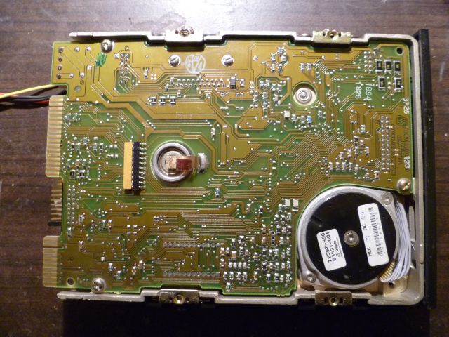
Vintage hard drives - Seagate ST-251


As the storage capacity of the hard disk drives emerges with no apparent limit (all hail Moore's law), old disks get obsolete no matter how ground-breaking they were a couple of years ago. I decided to collect some of the old hard disk drives here so that at least their memory would be conserved. The only selection rule for showing an old HDD I had is that I have to have that one somewhere at home :) so my choices will not be equalized in any sense, including technology, manufacturer and so on.

The first one I found is a Seagate ST-251 from 1994. Using MFM coding, this device was capable of a fantastic 40MB storage space using 6 heads on 3 plates. The maximum transfer rate is 625KB/s with its ST-412 MFM controller. It is an interesting fact that Seagate keeps a good record of its old products, even such an old device is on their webpage here.
These 5.25" units with their massive metallic case indeed represent some sort of everlasting elegance :)


Even though the electronics of the hard drive was restricted to the most basic functionality (and the rest was done by the control card) it seems quite complex: many application-specific ICs and lots of miscellaneous circuit elements can be spotted.

The PCB connector itself is a long time extinct part: on the left, the 34 pol connector is allocated for the MFM control signals, whereas the 20 pol on the right is for the MFM data R/W signals. The jumpers in the middle are dedicated to set the address of the drive, making it possible to chain up to 4 drives in a computer. Note that the power connector is already the standard PATA 4 pin connector supplying 5V/12V. An interesting consequence of the separate control card is that the bad sectors found during factory testing are printed on the case of the drive with the corresponding C/H/S values. Nowadays such maps are stored by the HDD electronics.


After removing the PCB, we get a good sight to the two motors. The one in the middle spins the plates at 3600 rpm and is most likely a brushless 3 phase motor. The other one in the corner is a stepper motor and moves the R/W heads above the plates. While steppers have eventually been replaced by more compact and lightweight solutions, the plate spinner motors are essentially the same even nowadays (they might be a bit smaller though).

These old and robust devices did not really follow today's trend of being low-power and silent. According to the data sheet, it consumes up to 12W and has a characteristic head-bang noise when starting up which is a result of the head calibration process in order to find track0. As a conclusion watch the video I made with the clean area cover removed so that we can see what is going on.


12.2.11

MRTG lang=C why and howto

In my previous post on MRTG, I showed how to plot various sensor and network traffic readings so that they can be easily visualized. In modern systems one can however run into another problem: in UTF-8 enviroments, MRTG starts to complain: 

~#:echo $LANG 
en_us.UTF-8 
~#:mrtg 

ERROR: Mrtg will most likely not work propperly when the environment
variable LANG is set to UTF-8. Please run mrtg in an environment
where this is not the case:

env LANG=C /usr/bin/mrtg

So we shall use the command line given above. However, simply setting LANG=C turns out not be enough, and we get further error messages with previously working mrtg.cfg file such as follows: 

~#:env LANG=C /bin/mrtg /etc/mrtg/mrtg.cfg --logging /var/log/mrtg.log 

...
2010-11-26 16:05:22 -- SNMPGET Problem for hrSystemUptime.0 sysName on public@localhost
 at /bin/mrtg line 658
2010-11-26 16:05:22 -- 2010-11-26 16:05:12: ERROR: Target[localhost.cpu0][_IN_] ' $target->[1]{$mode} ' did not eval into defined data
2010-11-26 16:05:22 -- 2010-11-26 16:05:12: ERROR: Target[localhost.cpu0][_OUT_] ' $target->[1]{$mode} ' did not eval into defined data
2010-11-26 16:05:32 -- SNMP Error: 
no response received

The problem turns out to be that the textual SNMP targets do not work anymore, and the numeric OIDs such as .1.3.6.1.2.1.25.3.3.1.2.768 have to be put in mrtg.cfg. Not only this is inconvenient, the proper numeric values have to be found as well. In order to do so, the snmptranslate tool can be used:

~#: snmptranslate HOST-RESOURCES-MIB::hrProcessorLoad.768 -On
.1.3.6.1.2.1.25.3.3.1.2.768

Here the main point is the -On switch, which translates the name of the OID to the corresponding numerical value. All textual targets in mrtg.cfg must be replaced using the output of this tool. This includes the previously discussed lm-sensors outputs as well. Here is an example for CPU usage:

# commented old one
#Target[localhost.cpu0]: hrProcessorLoad.768&hrProcessorLoad.768:public@localhost
#new one follows
Target[localhost.cpu0]:.1.3.6.1.2.1.25.3.3.1.2.768&.1.3.6.1.2.1.25.3.3.1.2.768:public@localhost 

and then MRTG works again!

7.12.10

Headless-only Virtualbox

Virtualbox is a versatile virtualization solution. That is, many virtual machines can be hosted on a single physical computer. This software is well supported under Linux, download and installation instructions for the binary package can be found here. Interestingly, although virtualization comes especially handy in server environments, Virtualbox demands most of the X-Windows system to be installed as a package dependency, even though command line operation and Remote Display (VRDP) as output device is supported in headless mode meaning that the graphic output of the guest operating system can be viewed with a RDP software such as Windows' built-in Remote Desktop Connection.
Luckily enough, such package dependencies can be circumvented, saving the system several hundreds of MBs of unnecessary packages at the expense of loosing all local graphic capabilities. But if you do not plan to install and use X anyways, then this will not be a problem.
The steps below are based on forum posts here and here. I however had to update those instructions to be useful for the current version 3.2. As usual, a Debian-based distribution is assumed, yet the adaption should be straightforward to other distributions as well.
Download the appropiate package from here and save it to ~/virtualbox/virtualbox.deb. Then:

#: cd virtualbox
#: dpkg --extract virtualbox.deb original
#: dpkg --control virtualbox.deb original/DEBIAN

Now we have the extracted package along with the dependency information in original/DEBIAN/control.
First we delete unnecessary files and dirs from the package:

#: rm -rf usr/lib/virtualbox/sdk usr/lib/virtualbox/VirtualBox usr/lib/virtualbox/VirtualBox.so usr/lib/virtualbox/VBoxSDL usr/lib/virtualbox/VBoxSDL.so usr/bin/VirtualBox usr/bin/VirtualBox.so usr/bin/VBoxSDL usr/lib/virtualbox/libQtGuiVBox.so.4

Now, resolving the dependency issue, the content of the original/DEBIAN/control has to be altered. The important part here is the part starting with "Depends:" where plenty of packages reside. For command line operation, only the following are necessary:

Depends: libc6 (>= 2.6), libcurl3-gnutls (>= 7.16.2-1), libgcc1 (>= 1:4.1.1), libssl0.9.8 (>= 0.9.8m-1), libstdc++6 (>= 4.4.0), libxml2 (>= 2.7.4), psmisc, adduser

Save the file, and the package is ready to be repacked and installed:
#: dpkg --build ~/virtualbox/original ~/virtualbox/repacked.deb
#: dpkg --install ~/virtualbox/repacked.deb

Note that after such a reconfiguration only VBoxHeadless can be used to start the virtual machines, and they can be configured using the VBoxManage command line tool.

29.11.10

Lm-sensors in net-snmp

Readout of integrated motherboard sensors was already a topic here, for VIA Epia boards and for WD Mybook World Edition as well. Such data is good to have visualized, so plotting it using MRTG was discussed too. This tool and its fundamental, net-snmp was designed to visualize network traffic data, so for sensor readings, an external script had to be constructed, which was quite inconvenient.
There is however a better way, briefly mentioned by lm-sensors.org, for which net-snmp has to be installed from source (download here, install instructions here) and has to be configured with the following options:
~$: cd net-snmp
~$: ./configure --with-mib-modules="ucd-snmp/lmsensorsMib" --with-ldflags="-lsensors" 
~$: make
~$: sudo make install

If installation was successful, lm-sensor readouts can be accessed via snmp, the same way as if they were polled by the command-line sensors tool:

~#: sensors

coretemp-isa-0000
Adapter: ISA adapter
Core 0:      +33.0 °C  (high = +78.0 °C, crit = +100.0 °C) 

coretemp-isa-0001
Adapter: ISA adapter
Core 1:      +32.0 °C  (high = +78.0 °C, crit = +100.0 °C) 

~#: snmpwalk -v 2c -c public localhost Sensors

LM-SENSORS-MIB::lmTempSensorsIndex.1 = INTEGER: 1
LM-SENSORS-MIB::lmTempSensorsIndex.2 = INTEGER: 2
LM-SENSORS-MIB::lmTempSensorsDevice.1 = STRING: Core 0
LM-SENSORS-MIB::lmTempSensorsDevice.2 = STRING: Core 1
LM-SENSORS-MIB::lmTempSensorsValue.1 = Gauge32: 33000
LM-SENSORS-MIB::lmTempSensorsValue.2 = Gauge32: 32000

Sadly, only CPU core temperatures can be read out for ICH8/ICH9 chipsets at the moment, still it is now way easier to integrate lm-sensor readings to net-snmp based logging and plotting tools such as MRTG.

28.11.10

Chocolate Fondue: Emergency Edition

Well, winter has come, and so has the cold weather, therefore a nice hot chocolate fondue could save life. This fondue set consists of three small glasses, one small ceramic bowl, one top of cookie box, and two candles (one for support and one for melting the chocolate chips).


7.9.10

Just a short note from Rome

Apparently the ticket vending machines of Trenitalia (Italian railway company) still run on OS/2 Warp 4. I just saw one of them rebooting :cool:

28.8.10

HP 5036A Microprocessor Lab

I just got this machine possessed. It is a microprocessor demonstration board based on the Intel 8085 CPU meaning that it was built for educational use and to demonstrate the capabilities of Intel's early 8 bit CPUs. According to a very few information on the web it was produced from 1978 through the early 80's by Hewlett-Packard.

First impressions:

The nice leather briefcase makes the appearance really elegant, something that is missed from new and modern equipment. Also, push buttons are built for eternity, no lifetime by design.


Technical data:

Manufacturer: Hewlett-Packard;
CPU: NEC D8085AC (Intel 8085 compatible);
CPU clock: 2 MHz using external 4 MHz crystal;
ROM: 2 KB external  SY2316 (mapped from 0x0000 to 0x07FF);
RAM: 1 KB external 2xSY2114 (mapped from 0x0800 to 0x0BFF);
Keyboard: built-in hexadecimal keyboard plus additional function keys;
Display: 6 digit LED display;
I/O: one 8 bit port with LED indicators and DIP switches;
On-board speaker;
Additional jumpers are provided to simulate circuit failures.

Note: Regarding to the ROM and RAM chips, I could only recover the manufacturer called Synertek, which was founded in 1973, bought by Honeywell in 1979, and finally closed off in 1985. Some photo on their products can be found here.

Operation:

Upon a successful boot, the message "uLAb UP" is visible on the LED displays. Storing new programs in the RAM is possible using the push button interface. These among built-in code can be run by simply pressing "Fetch Address", setting the appropriate memory address and pressing "Run". Single line execution is also possible. This is a notable example for a compact yet powerful user interface from times before LCD/TFT displays.

In order to ease learning, several built-in demos are accessible. Notable examples are:
the Rocket Launcher demo on address 0x05F9;
Display test with moving pattern on address 0x055A;
Random Tone Generator on address 0x053E;
Stopwatch on address 0x0662.


The documentation is in fact fascinating: a 450 page book entitled Practical Microprocessor is included in the briefcase. This is not only a tutorial but a complete documentation including ROM listing, schematics and some brief datasheets as well. 


21.7.10

VIA Epia Homeserver Project - HDD Power Saving

The power consumption of a hard disk cannot be neglected in a system designed to be of low consumption. For the operating system, a flash based drive (SSD or CF disk) is a good solution, yet for high volume storage this is usually not affordable. Recently, hard disk drives in the terrabyte range especially designed to be power efficient have been announced such as Western Digital's Greenpower series or the Ecogreen drives of Samsung. Their offer is  a substantial decrease of power consumption (up to 40% claimed) at the expense of somewhat slower operation. This is achieved for instance by spinning only at 5400rpm instead of 7200rpm, which is still reasonable for media storage or backup and even for office applications.

This tutorial is on setting up a Samsung Ecogreen HD154UI drive in my Via Epia homeserver. The goal was to make use of the power saving features that the drive has to offer using the native linux tool hdparm.
This is a very powerful (and therefore dangerous!) program that can read or set many parameters of PATA or SATA drives in order to tune performance, power consumption, or even hot swap disks. As of the writing of this tutorial, I use hdparm v8.9, note that syntax might change later on. It is also important that the proper driver for the PATA and SATA chipset is either compiled in the kernel or loaded as a module.

All functionality of hdparm is available through command line, yet it is better to use /etc/hdparm.conf to adjust parameters, as it will make those effective after each system boot. Mine looks like this:

/dev/sda {
    dma = on
    interrupt_unmask = on
    mult_sect_io = 16
    write_cache = on
    transfer_mode = 70
    io32_support = 1
    apm = 1
    spindown_time = 60
}

with dma = on meaning DMA instead of PIO (this is the default anyway). Interrupt_unmask = on allowing the system to process multiple IRQs at the same time. mult_sect_io = 16 determines the number of simultaneously transferred blocks (safe to set it to its maximum value). Write_cache = on tells the system to cache write operations. This might be dangerous if a power-cut occurs, yet usually is a good idea to set. Transfer_mode = 70 sets UDMA6. Other UDMA, DMA, PIO settings can be found here. io32_support = 1 is quite straightforward and should be set as well. 

The rest are the power saving parameters: apm = X sets how aggressively the drive would enter power saving modes with 1 equals the lowest consumption and 255 means no power saving and maximum performance. Note that X being equal to 128 or above, no spindown is allowed. As I use my disk mostly for storage, I chose the lowest power setting, X=1. Spindown_time sets the length of inactivity before the drive spins down in 5 sec units, so that 60 means 5 minutes timeout. If you experience that you have to wait often to the drive to spin up, consider setting this parameter higher. 

It is very important to note that not only disk I/O but any disk operation including checking drive health status using smartmontools will cause the drive to spin up. This means that periodic checking of drive health or temperature will render this setting essentially useless.

If hdparm.conf is set up correctly, the new parameters will be effective upon the next boot and can be checked:

~#: hdparm -i /dev/sda

/dev/sda:

 Model=SAMSUNG HD154UI                         , FwRev=1AG01118, SerialNo=S1XWJ1KZ300133     
 Config={ Fixed }
 RawCHS=16383/16/63, TrkSize=34902, SectSize=554, ECCbytes=4
 BuffType=DualPortCache, BuffSize=32767kB, MaxMultSect=16, MultSect=?16?
 CurCHS=16383/16/63, CurSects=16514064, LBA=yes, LBAsects=18446744072344861488
 IORDY=on/off, tPIO={min:120,w/IORDY:120}, tDMA={min:120,rec:120}
 PIO modes:  pio0 pio1 pio2 pio3 pio4
 DMA modes:  mdma0 mdma1 mdma2
 UDMA modes: udma0 udma1 udma2 udma3 udma4 udma5 *udma6
 AdvancedPM=yes: unknown setting WriteCache=enabled
 Drive conforms to: unknown:  ATA/ATAPI-3,4,5,6,7

 * signifies the current active mode


20.7.10

VIA Epia Homeserver Project - CPU Frequency Scaling

Even though the VIA Epia platform is designed to be very power efficient out of the box, it can be made even better. One tool to do this is the CPU frequency scaling that is supported by both recent linux kernels and the Eden CPU. Specifically, the processor of the EN12000EG board runs at 1200MHz by default, but can go down to as low as 400MHz, resulting not only in reduced power consumption, but decreased heating as well. This especially comes handy for fanless systems, eventually resulting in lower die temperature and longer life span.

System setup

In order to utilize this feature the following kernel modules have to compiled (=Y), or installed as module (=M):
X86 CPU: CONFIG_X86_CPU=y 
VIA C7 CPU: CONFIG_MVIAC7=y

ACPI: (not sure if these are necessary, yet they won't hurt...)
CONFIG_ACPI=y 
CONFIG_ACPI_PROCESSOR=y

CONFIG_X86_PCC_CPUFREQ=y
CONFIG_X86_ACPI_CPUFREQ=y

(Note: # CONFIG_X86_E_POWERSAVER is not set because it is considered to be dangerous as no hardware limits are taken into account while tuning the CPU clock. However, I did not find any remarks nor observations on this driver).

CONFIG_CPU_FREQ=y
CONFIG_CPU_FREQ_TABLE=y
CONFIG_CPU_FREQ_STAT=y
CONFIG_CPU_FREQ_STAT_DETAILS=y
CONFIG_CPU_FREQ_DEFAULT_GOV_CONSERVATIVE=y
CONFIG_CPU_FREQ_GOV_PERFORMANCE=y
CONFIG_CPU_FREQ_GOV_POWERSAVE=y
CONFIG_CPU_FREQ_GOV_USERSPACE=y
CONFIG_CPU_FREQ_GOV_ONDEMAND=y
CONFIG_CPU_FREQ_GOV_CONSERVATIVE=y

The options above sets the Governors that can be used later on. As you can see, there are five alternatives, Performance, Powersave, Userspace, Ondemand and Conservative.
The character of each governors  are the following:
  •  Performance: simply sets the highest available CPU frequency. Usually this is the default in stock kernels.
  • Powersave: sets the lowest available frequency no matter what the system load is.
  • Userspace: the CPU clock can be set manually thorugh the /sys interface
  • Ondemand: switches between the highest and lowest frequency according to the system load. The corresponding thresholds can be set via the the /sys interface. 
  • Conservative: such as above, although it can set intermediate frequency values as well. The trade-off is higher latency.
The default governor is quite straightforward to set, here I chose Conservative. In this tutorial, only this governor is discussed in detail, however, most of the arguments are straightforward to use for the others as well.

Test results

Upon booting with the new kernel and/or loading the corresponding modules, the influence of the governor is already visible (remember, Conservative governor is set):

#:  cat /proc/cpuinfo
processor    : 0
vendor_id    : CentaurHauls
cpu family    : 6
model        : 10
model name    : VIA Esther processor 1200MHz
stepping    : 9
cpu MHz        : 400.000
cache size    : 128 KB
fdiv_bug    : no
hlt_bug        : no
f00f_bug    : no
coma_bug    : no
fpu        : yes
fpu_exception    : yes
cpuid level    : 1
wp        : yes
flags        : fpu vme de pse tsc msr pae mce cx8 apic sep mtrr pge cmov pat clflush acpi mmx fxsr sse sse2 tm nx pni est tm2 rng rng_en ace ace_en ace2 ace2_en phe phe_en pmm pmm_en
bogomips    : 797.99
clflush size    : 64
cache_alignment    : 64
address sizes    : 36 bits physical, 32 bits virtual
power management:

showing that the CPU clock is set to 400MHz. If, however, some CPU intensive process is started (compiling kernel or some application is a good check :)) then increased demand results in increased clock frequency:

#:  cat /proc/cpuinfo
processor    : 0
vendor_id    : CentaurHauls
cpu family    : 6
model        : 10
model name    : VIA Esther processor 1200MHz
stepping    : 9
cpu MHz        : 1200.000
cache size    : 128 KB
fdiv_bug    : no
hlt_bug        : no
f00f_bug    : no
coma_bug    : no
fpu        : yes
fpu_exception    : yes
cpuid level    : 1
wp        : yes
flags        : fpu vme de pse tsc msr pae mce cx8 apic sep mtrr pge cmov pat clflush acpi mmx fxsr sse sse2 tm nx pni est tm2 rng rng_en ace ace_en ace2 ace2_en phe phe_en pmm pmm_en
bogomips    : 2393.89
clflush size    : 64
cache_alignment    : 64
address sizes    : 36 bits physical, 32 bits virtual
power management:

Detailed statistics is available via the /sys interface:

#: cat /sys/devices/system/cpu/cpu0/cpufreq/stats/time_in_state
1200000 38445
400000 42604408

which tells us both the available frequency values (in kHz) and the corresponding time that the CPU spent in that state in 10ms.

#: cat /sys/devices/system/cpu/cpu0/cpufreq/stats/trans_table
   From  :    To
         :   1200000    400000
  1200000:         0        51
   400000:        50         0 

This command provides a nice matrix in which the starting and end frequency for each transition is observed. Note that as the system boots up using the higher value, the difference of one means that now the clock is equal to the lower value.

The current frequency can be obtained as above by interrogating /proc/cpuinfo, however /sys tells it as well:

#: cat /sys/devices/system/cpu/cpu0/cpufreq/scaling_cur_freq
400000

The operation of this governor can be tuned via the nodes in /sys/devices/system/cpu/cpu0/cpufreq/conservative (followed by their default values):

down_threshold (20)
freq_step (5)
ignore_nice_load (0)
sampling_down_factor (1)
sampling_rate (200000)
sampling_rate_max (4294967295)
sampling_rate_min (200000)
up_threshold (80)

I however advise to be careful tampering with them. As each clock transition takes time the penalty can be serious performance degrade if the system is set to change frequency too often. On the other hand, increasing power consumption and heating is the result of too soft settings.

Conclusions

Using the Conservative governor is a reasonable improvement for my VIA Epia box, as the system now spends most of its time (over 99%!) in 400MHz instead of 1200MHz. In theory, however, some degradation of performance is associated with tuning the CPU frequency (as the clock transition takes time to occur), this was not observable for my system. 

Sadly enough, the governor was not able to tune the CPU clock continuously, it rather switched between the highest and lowest available values. Because of this, the Conservative and Ondemand governors essentially equivalent on this system. I am not sure if using CONFIG_X86_E_POWERSAVER instead of the default ACPI cpufreq driver solve this problem, this is to be tested.